- 您现在的位置:买卖IC网 > Sheet目录1991 > CS4364-CQZR (Cirrus Logic Inc)IC DAC 103DB 24BIT 6CH 48-LQFP
DS619F1
21
CS4364
4.2
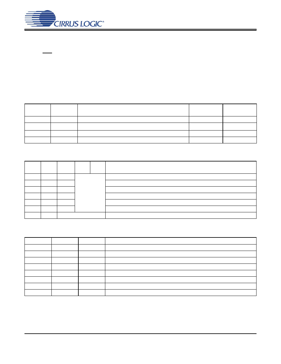
Mode Select
In Hardware Mode, operation is determined by the Mode Select pins. The states of these pins are continu-
ally scanned for any changes; however, the mode should only be changed while the device is in reset
(RST pin low) to ensure proper switching from one mode to another. These pins require connection to sup-
ply or ground as outlined in Figure 7. For M0, M1, and M2, supply is VLC. For M3 and M4, supply is VLS.
In Software Mode, the operational mode and data format are set in the FM and DIF registers. See “PCM
M1
(DIF1)
M0
(DIF0)
DESCRIPTION
FORMAT
FIGURE
00
Left Justified, up to 24-bit data
0
01
I2S, up to 24-bit data
1
10
Right Justified, 16-bit Data
2
11
Right Justified, 24-bit Data
3
Table 4. PCM Digital Interface Format, Hardware Mode Options
M4
M3
M2
(DEM)
M1
M0
DESCRIPTION
00
0
Single-Speed without De-Emphasis (4 kHz to 50 kHz sample rates)
00
1
Single-Speed with 44.1 kHz De-Emphasis; see Figure 16
01
0
Double-Speed (50 kHz to 100 kHz sample rates)
01
1
Quad-Speed (100 kHz to 200 kHz sample rates)
10
0
Auto Speed-Mode Detect (32 kHz to 200 kHz sample rates)
10
1
Auto Speed-Mode Detect with 44.1 kHz De-Emphasis; see Figure 16
11
DSD Processor Mode
Table 5. Mode Selection, Hardware Mode Options
M2
M1
M0
DESCRIPTION
00
0
64x oversampled DSD data with a 4x MCLK to DSD data rate
00
1
64x oversampled DSD data with a 6x MCLK to DSD data rate
01
0
64x oversampled DSD data with a 8x MCLK to DSD data rate
01
1
64x oversampled DSD data with a 12x MCLK to DSD data rate
10
0
128x oversampled DSD data with a 2x MCLK to DSD data rate
10
1
128x oversampled DSD data with a 3x MCLK to DSD data rate
11
0
128x oversampled DSD data with a 4x MCLK to DSD data rate
11
1
128x oversampled DSD data with a 6x MCLK to DSD data rate
Table 6. Direct Stream Digital (DSD), Hardware Mode Options
发布紧急采购,3分钟左右您将得到回复。
相关PDF资料
CS4382A-DQZ
IC DAC 8CH 114DB 192KHZ 48-LQFP
CS4384-CQZR
IC DAC 8CH 103DB 192KHZ 48-LQFP
CS4385-DQZR
IC DAC 8CH 114DB 192KHZ 48-LQFP
CS4391A-KZZR
IC DAC 24BIT 192KHZ W/VC 20TSSOP
CS4392-KZZ
IC DAC 24BIT 192KHZ W/VC 20TSSOP
CS4397-KSZ
IC DAC 24BIT MULTY STNDRD 28SOIC
CS4398-CZZ
IC DAC 120DB 192KHZ W/VC 28TSSOP
CS43L22-CNZR
IC DAC W/HDPN & SPKR AMPS 40-QFN
相关代理商/技术参数
CS4364-DQZ
制造商:CIRRUS 制造商全称:Cirrus Logic 功能描述:103 dB, 192 kHz 6-Channel D/A Converter
CS4364-DQZR
制造商:CIRRUS 制造商全称:Cirrus Logic 功能描述:103 dB, 192 kHz 6-Channel D/A Converter
CS4365
制造商:CIRRUS 制造商全称:Cirrus Logic 功能描述:114 dB, 192 kHz 6-Channel D/A Converter
CS4365_07
制造商:CIRRUS 制造商全称:Cirrus Logic 功能描述:114 dB, 192 kHz 6-Channel D/A Converter
CS4365_08
制造商:CIRRUS 制造商全称:Cirrus Logic 功能描述:114 dB, 192 kHz 6-Channel D/A Converter
CS4365-CQZ
功能描述:音频数/模转换器 IC 6-Ch DAC 24-Bit 192kHz w/DSD & LLDF RoHS:否 制造商:Texas Instruments 转换器数量: 分辨率:16 bit 接口类型:I2S, UBS 转换速率: 信噪比:98 dB 工作电源电压:5 V DAC 输出端数量:2 工作温度范围:- 25 C to + 85 C 电源电流:23 mA 安装风格:SMD/SMT 封装 / 箱体:TQFP-32 封装:Reel
CS4365-CQZR
功能描述:数模转换器- DAC IC 24bit 6Ch DAC w/DSD Sup/Lw-Ltnc DF RoHS:否 制造商:Texas Instruments 转换器数量:1 DAC 输出端数量:1 转换速率:2 MSPs 分辨率:16 bit 接口类型:QSPI, SPI, Serial (3-Wire, Microwire) 稳定时间:1 us 最大工作温度:+ 85 C 安装风格:SMD/SMT 封装 / 箱体:SOIC-14 封装:Tube
CS4365-DQZ
功能描述:数模转换器- DAC 6-Ch DAC 24-Bit 192kHz w/DSD & LLDF RoHS:否 制造商:Texas Instruments 转换器数量:1 DAC 输出端数量:1 转换速率:2 MSPs 分辨率:16 bit 接口类型:QSPI, SPI, Serial (3-Wire, Microwire) 稳定时间:1 us 最大工作温度:+ 85 C 安装风格:SMD/SMT 封装 / 箱体:SOIC-14 封装:Tube